Now to explain the somewhat complicated method of calculating the clutch pack clearances to ensure the selective circlip thickness is correct. This is critical on this gearbox as the clutches have fluid balanced pistons, that clearance has to be within tolerance.
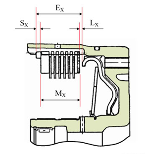
Mx is the height of your stack described below (at 200N force)
Ex is the available height in the clutch body
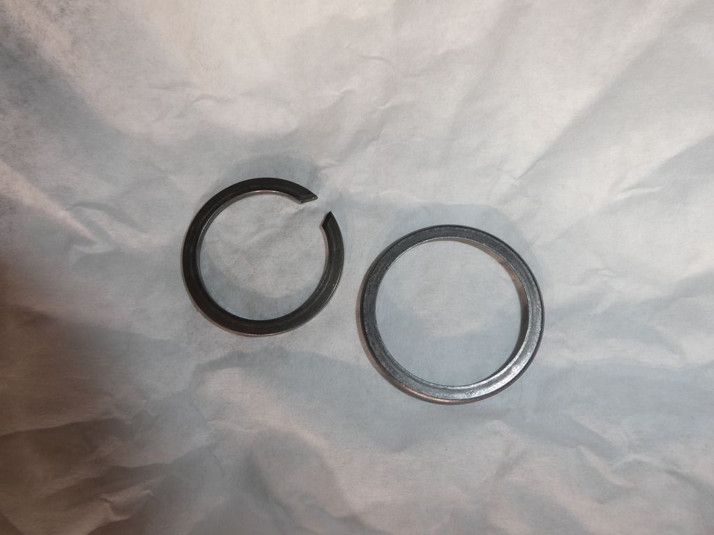
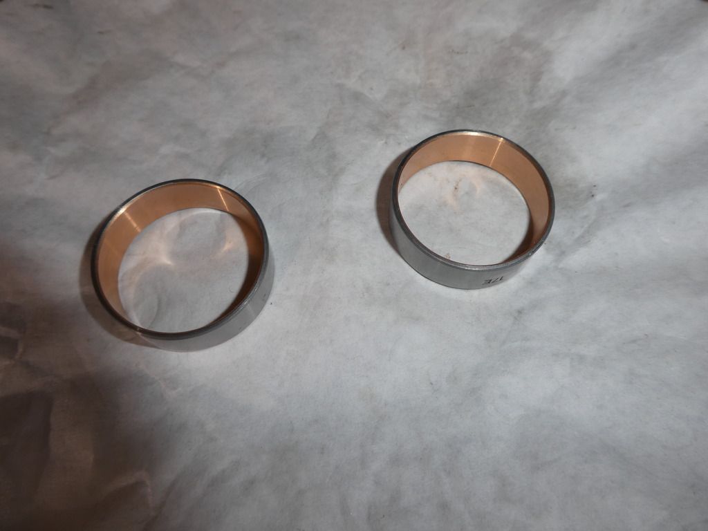
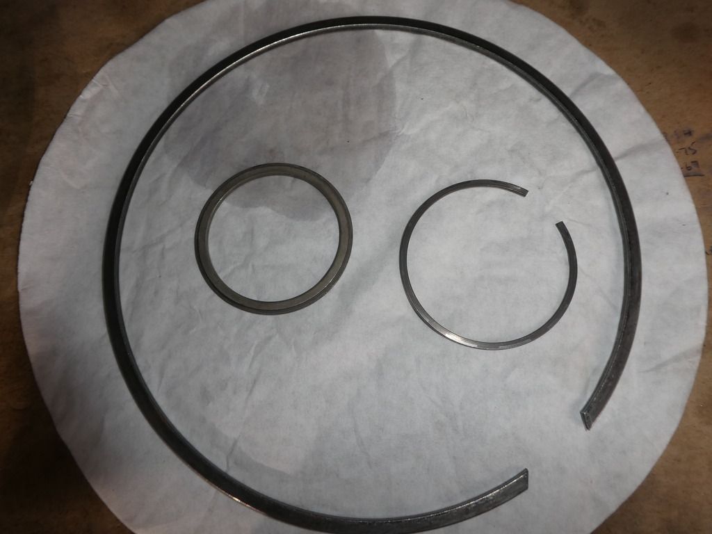
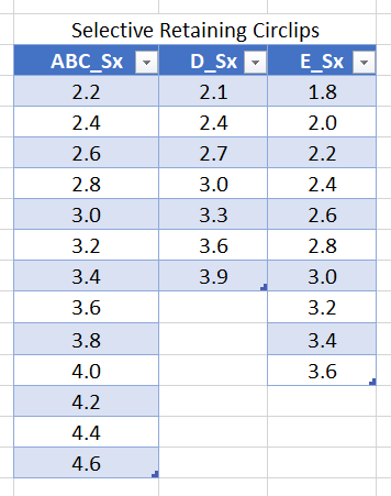
Sx is the thickness of the selective circlip (ALWAYS measure it, dont assume you bought a 2.4mm it will be 2.4mm!)
Lx is the allowable clearance you are targetting to be within specified tolerances
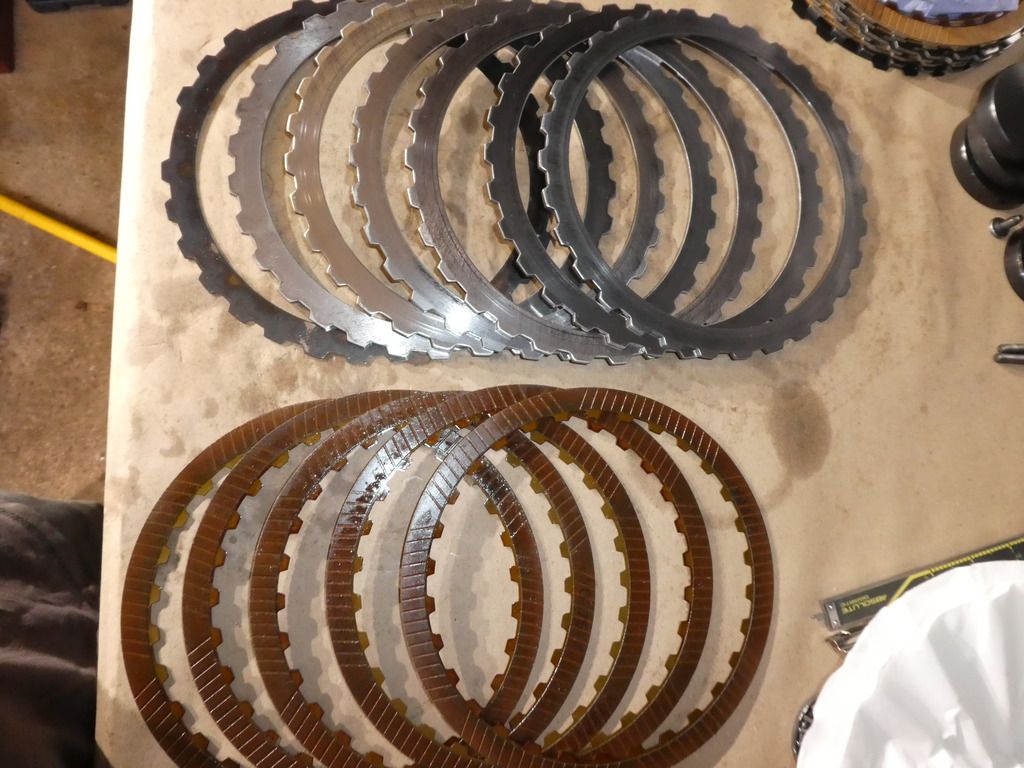
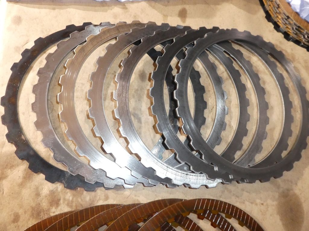
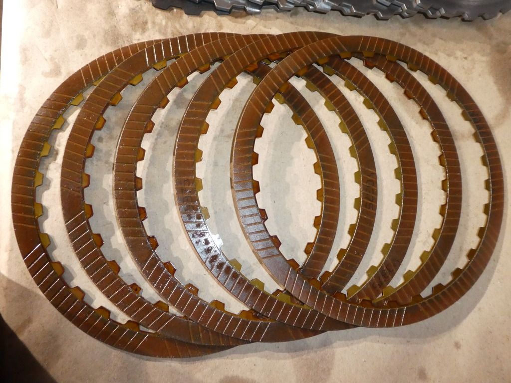
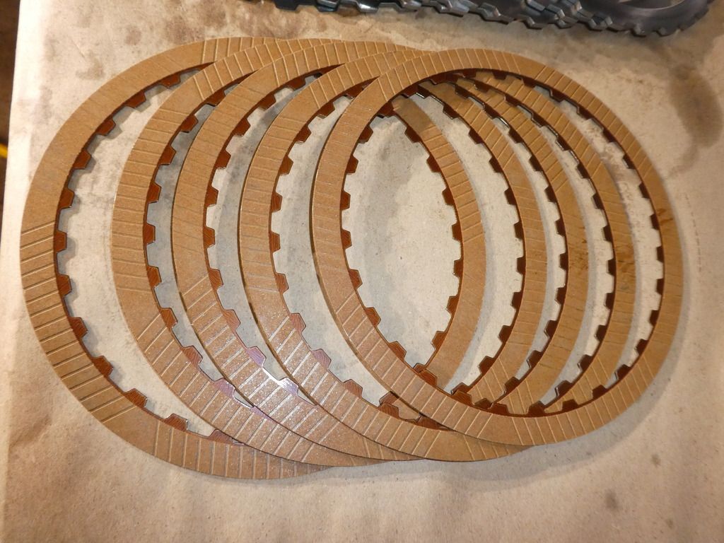
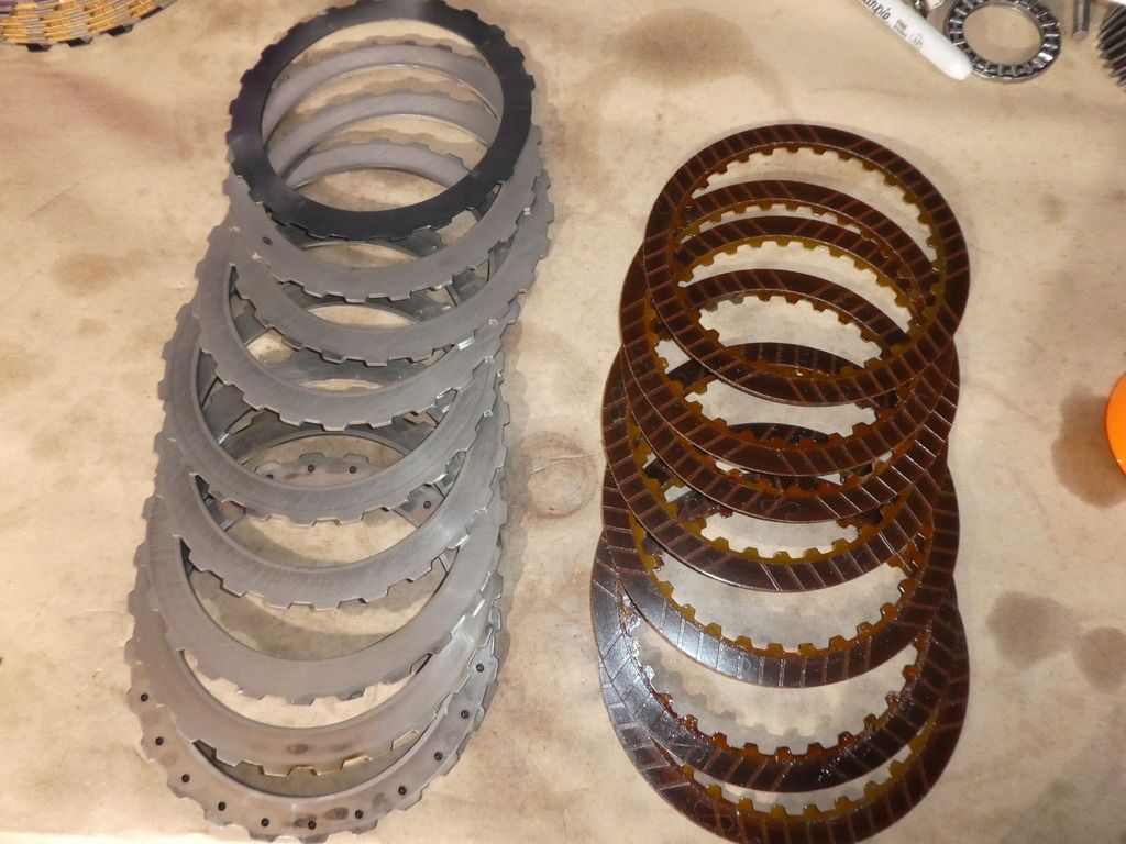
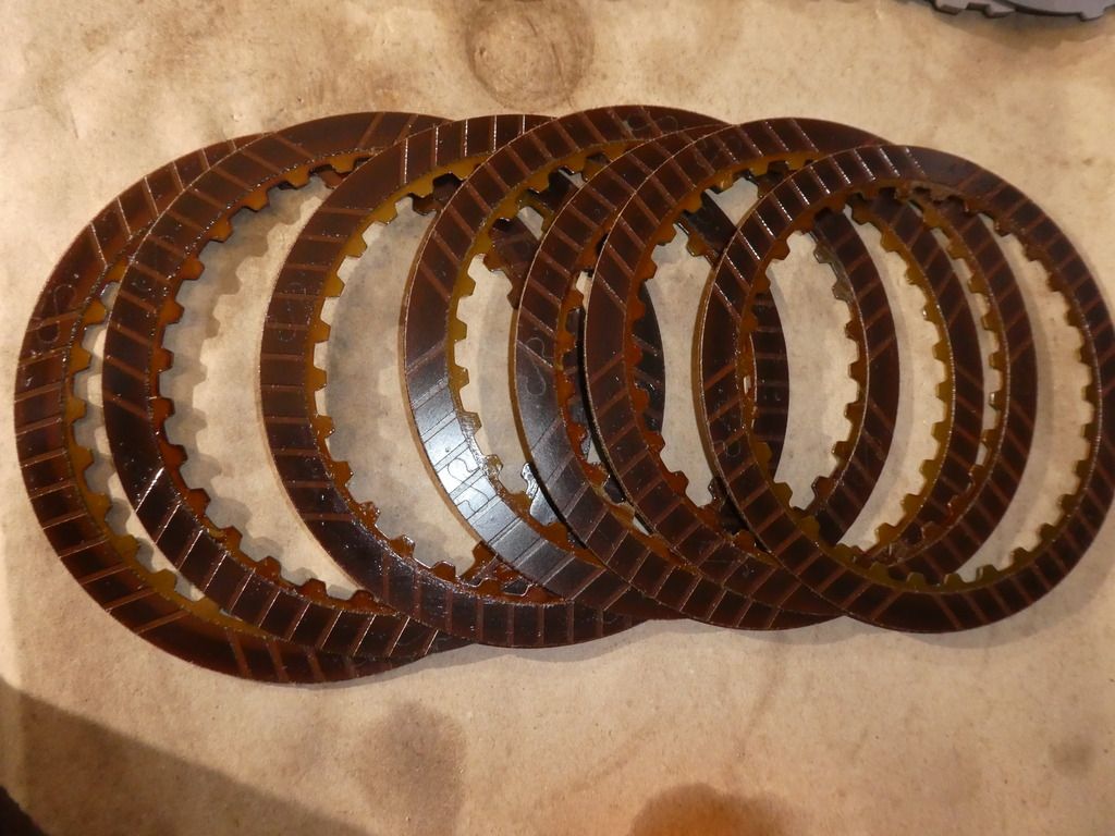
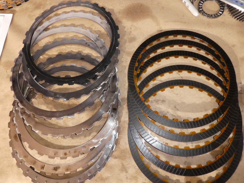
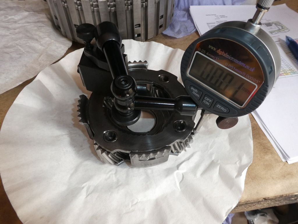
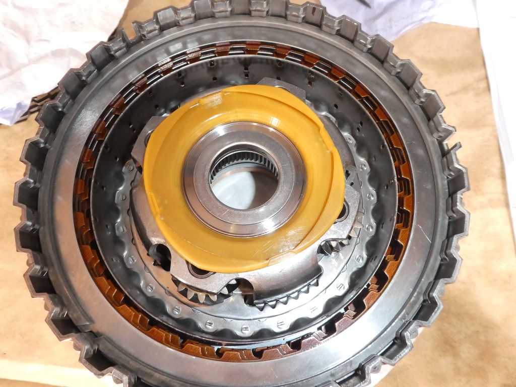
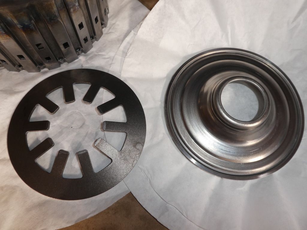
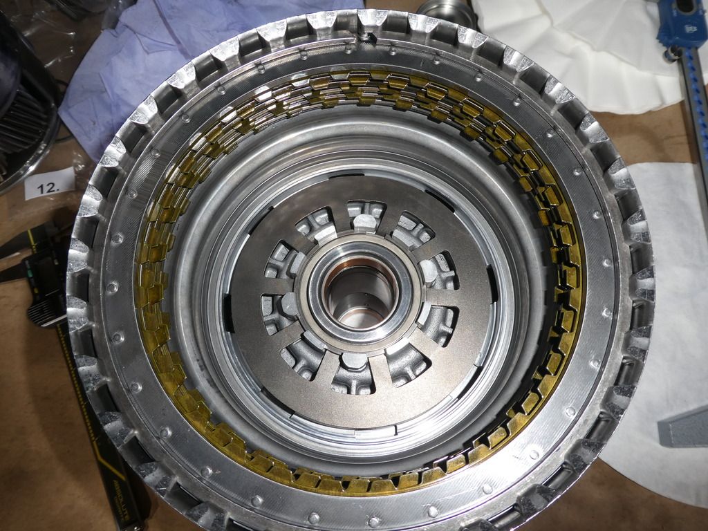
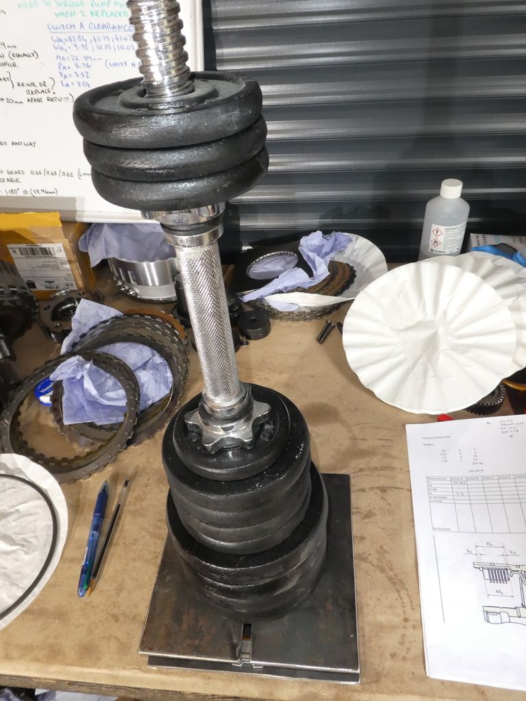
To do this you need to assemble the frictions and steels including the wave washer, the top-most steel which is normally thicker - and place on that assembly a 200N force. This is so that the wave washer is partially compressed, as it is in service. To work out what mass (weight in laymans terms) you need for an equivalent 200N force you just need to divide the 200N by gravity. In my case I collected a few weights I had which equated to 20.6kg; which is calculated at 202N (close enough!)
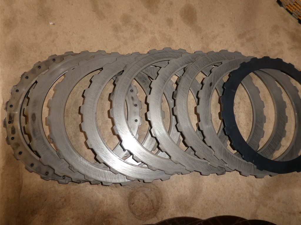
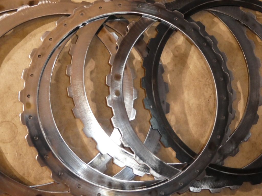
With this assembly you can measure the thickness of the stack (Mx) and log it. Do this for clutches A, B, C, D, E. You will need a DTI with travel of 25-32mm, or a depth gauge vernier; a DTI is (generally) more accurate. As you can see I put a convenient slot in the top plate to use for the DTI (and yes account for any such top plate in your mass calculation!)
You can of course spend a small fortune on the ZF tooling fr these measurements;or like me improvise

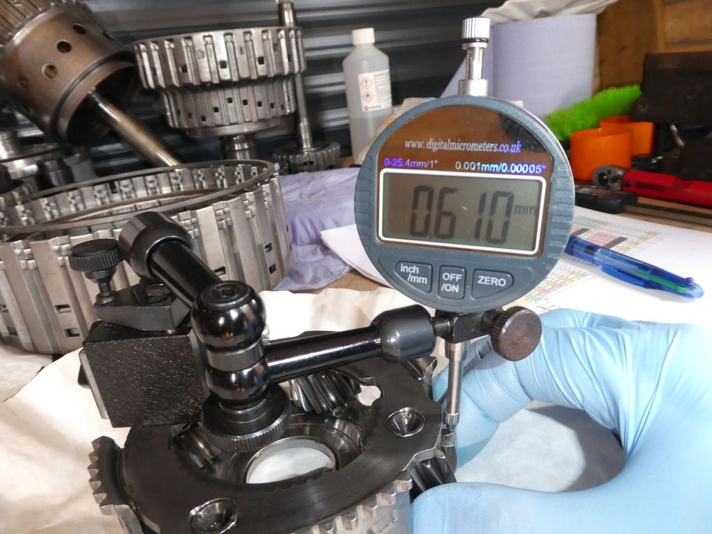
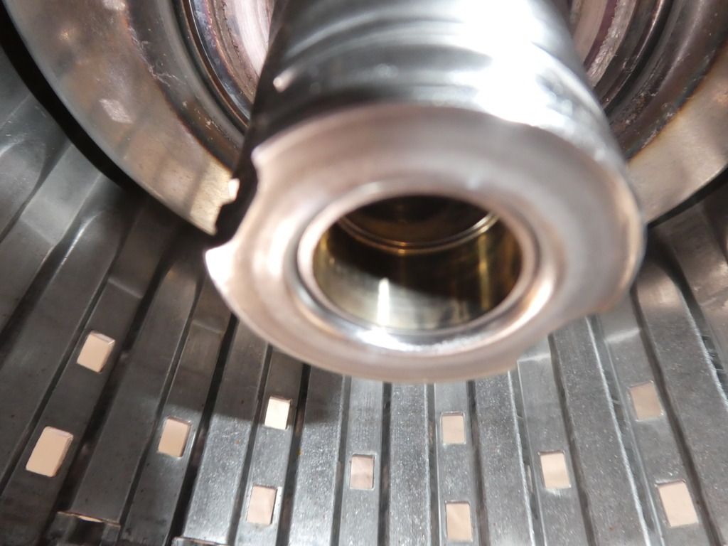
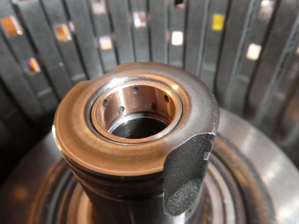
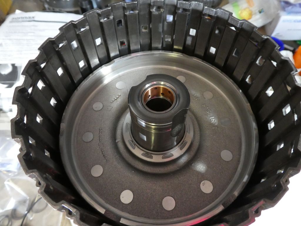
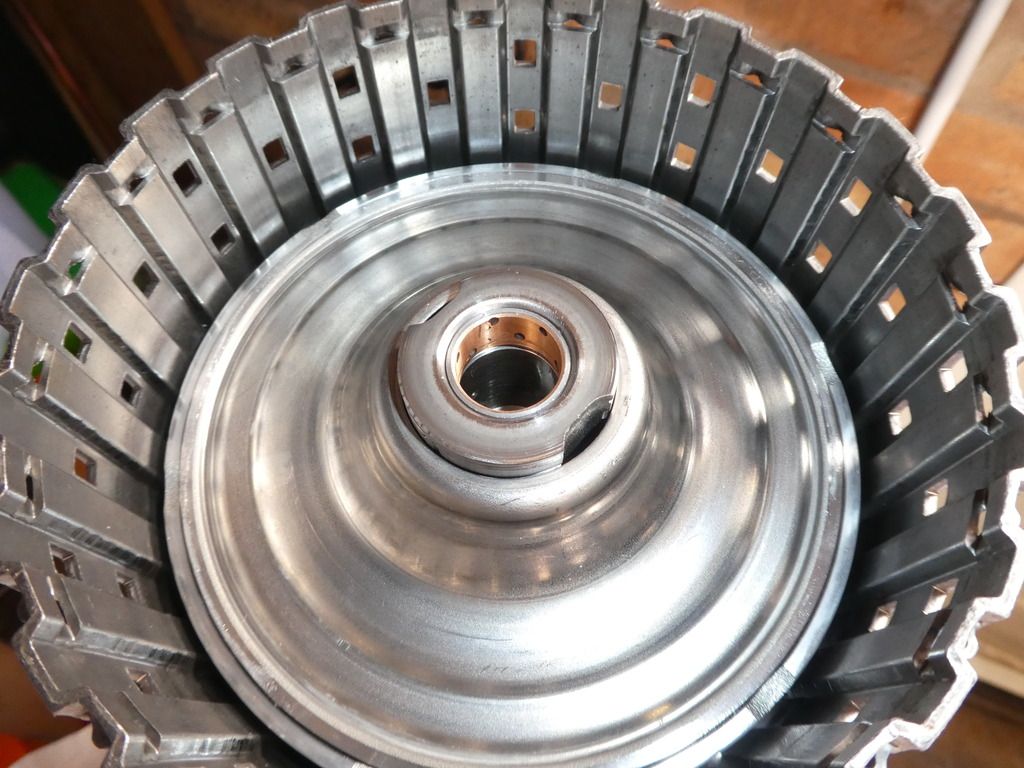
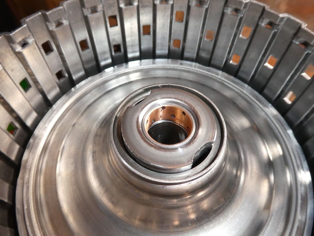
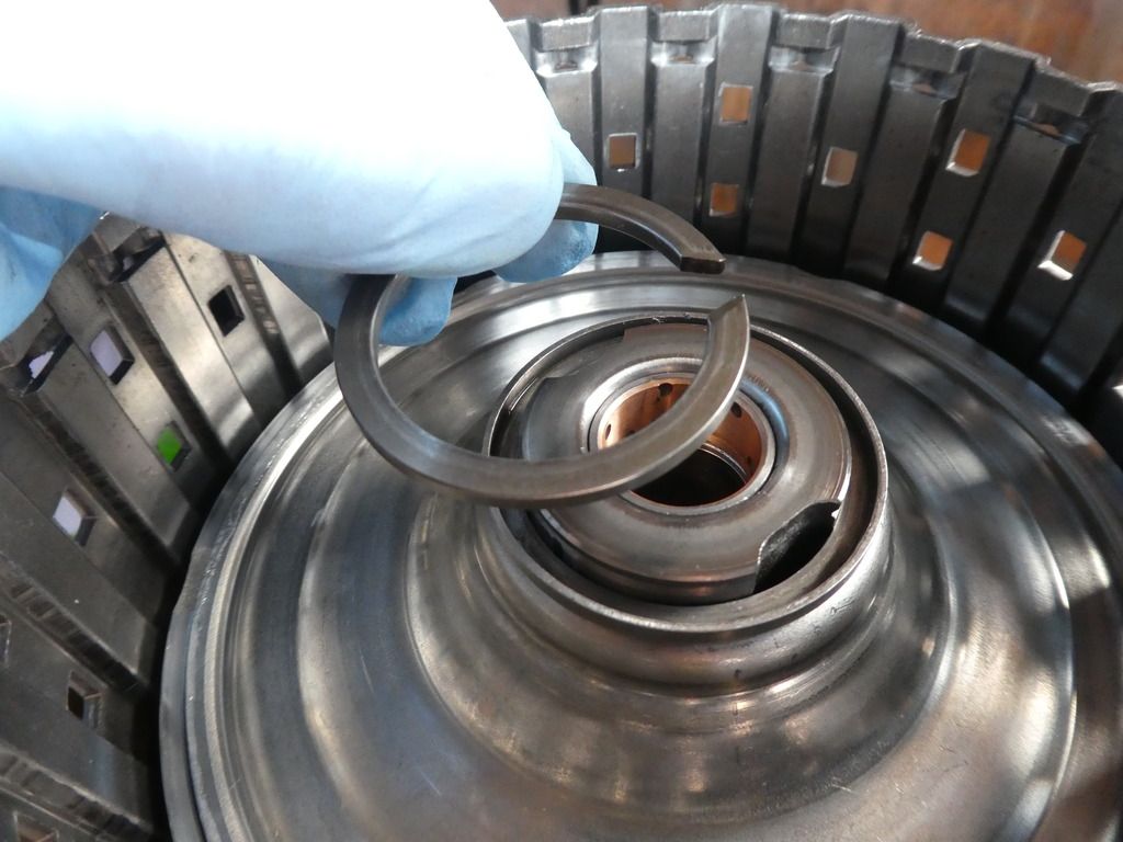
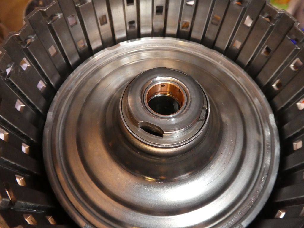
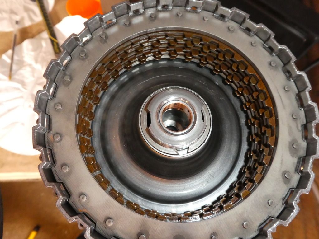
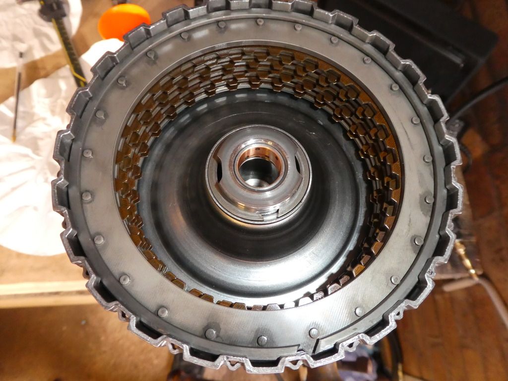
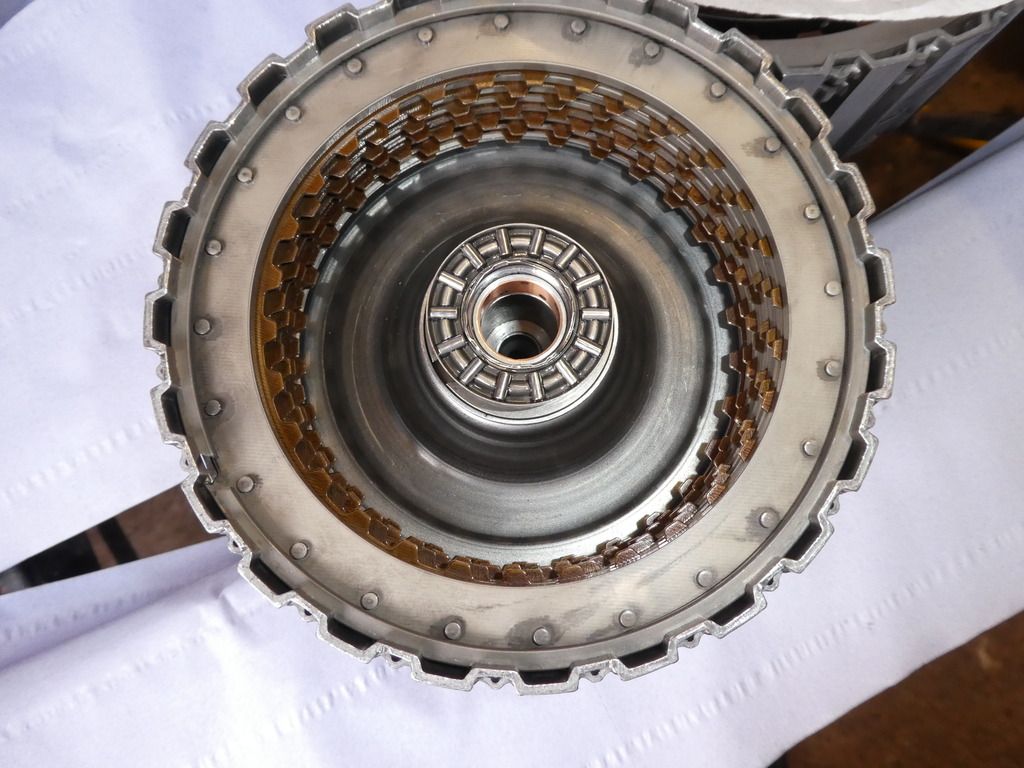
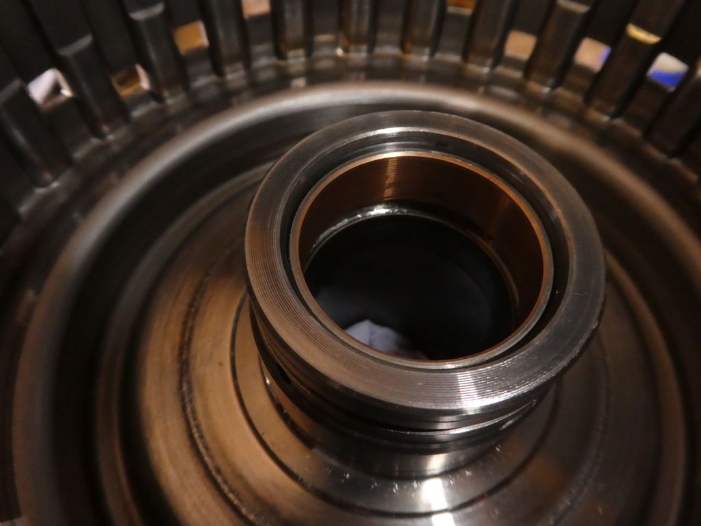
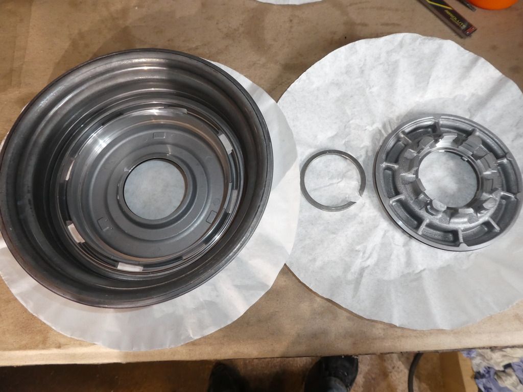
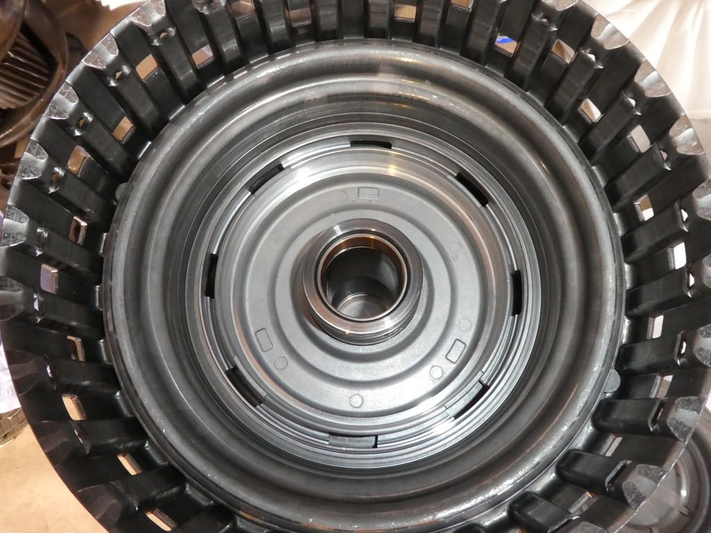
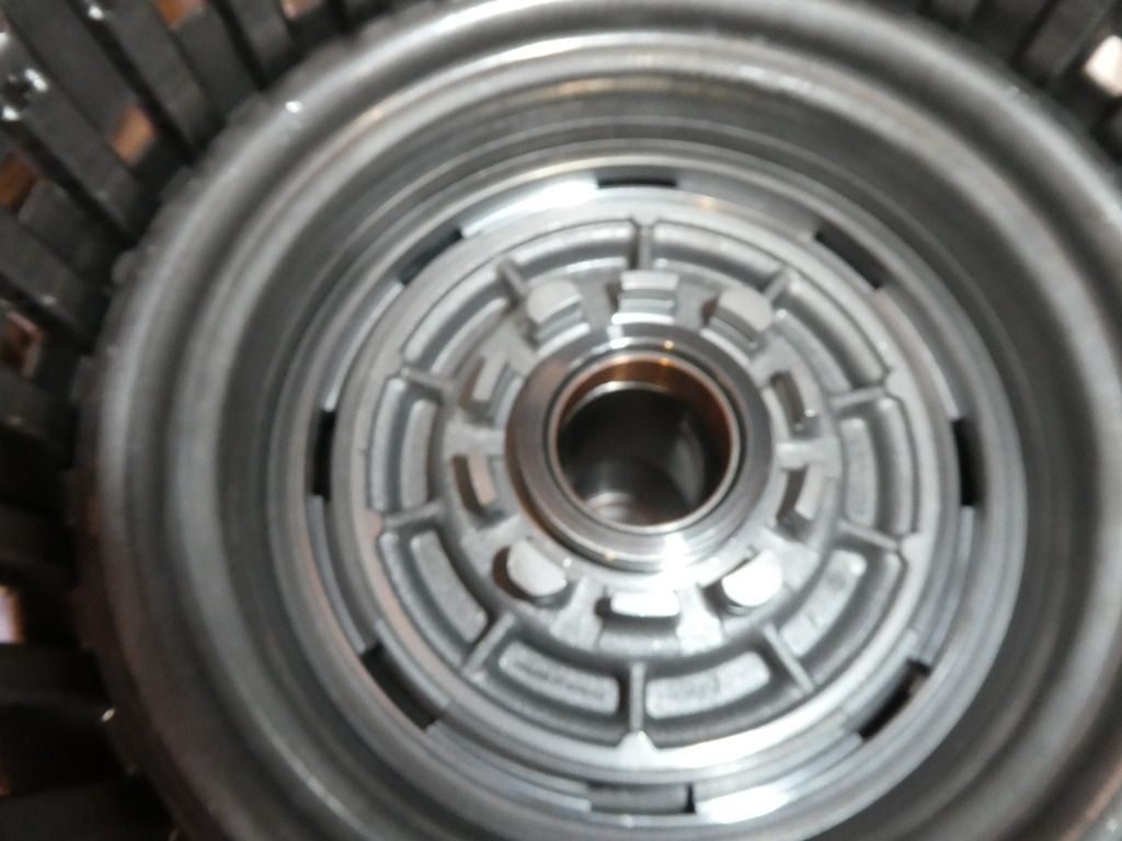
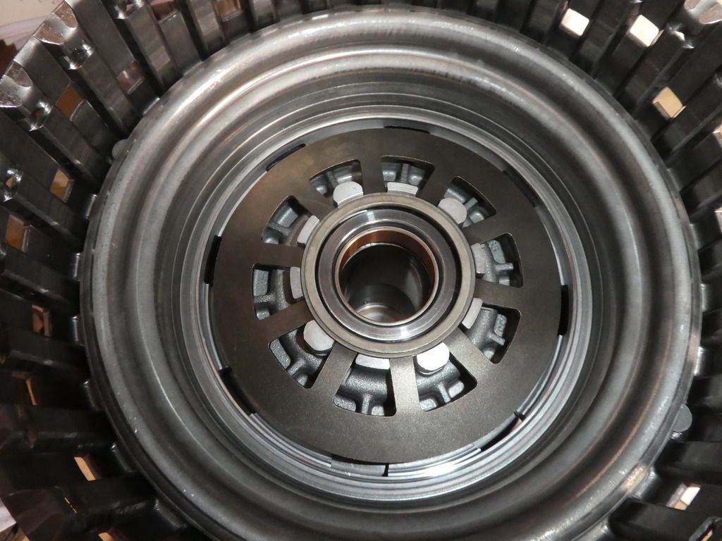
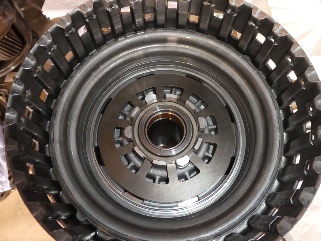
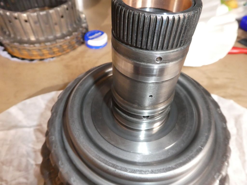
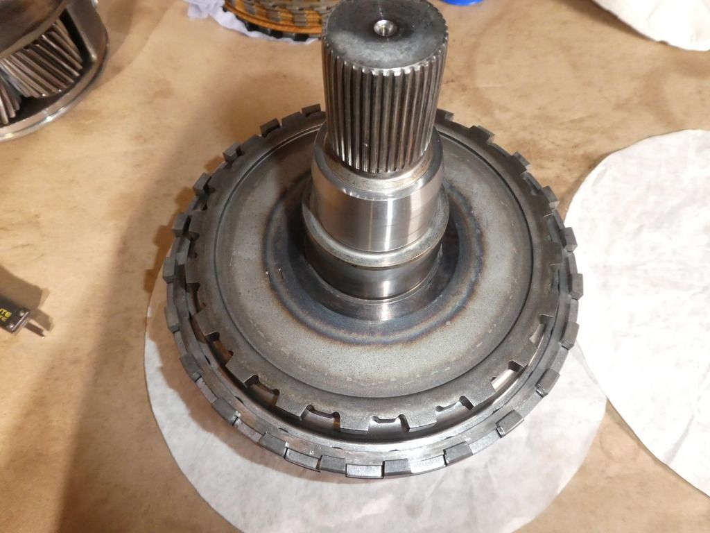
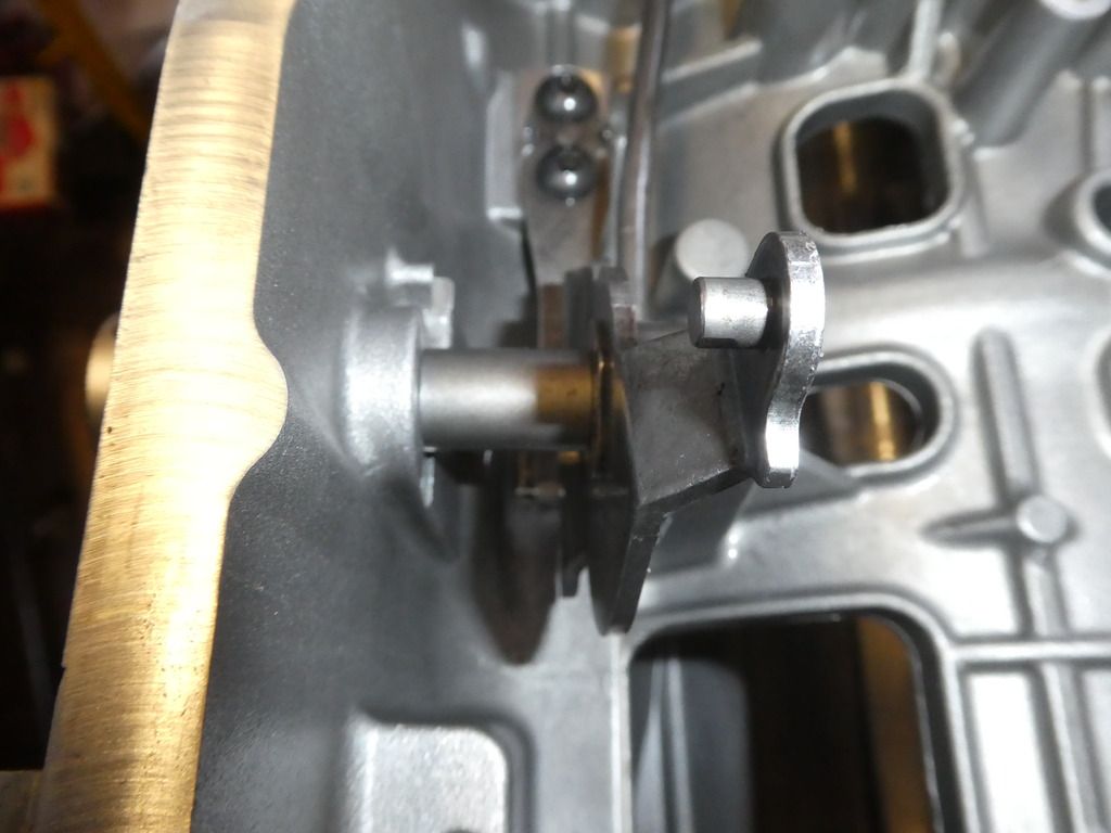
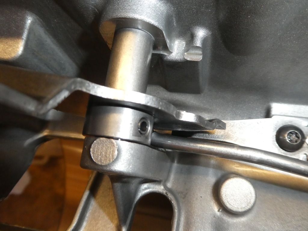
Once you have this you then need to measure the available height for the clutch stack (Ex) in the clutch assemblies; that is the height from the piston to the top-most edge of the retaining circlip. For this I use a digital depth gauge vernier; datum at the piston seated from the top edge of the clutch body (no clutch pack fitted) and measure the offset to the top of the circlip (clutch pack fitted) whilst lifting the clutch pack firmly against the circlip with a small flat screwdriver between the final steel and the clip.
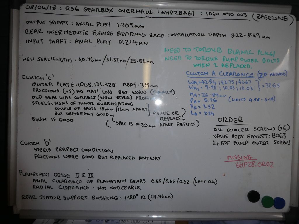
Armed with these measurements and the known current circlip thicknesses (Sx) you can tabulate all of this to determine whether you need to change the cirlip. I have an image of my results here but if anyone wants this excel file just pm me.
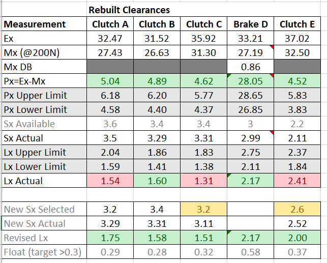
The bottom line for me, noting in my usual padantic methodology I aim for a tolerance of 0.3 below the upper tolerance limit Lx (ensuring not too tight to bind but leaving max allowance for wear) that I need to change 2 circlips; I use Clutch B circlip for Clutch A; I use Clutch C circlip for Clutch B; I need a new circlip for Clutch C; Clutch D is good with the existing circlip; I need a new circlip for Clutch E.
The other thing to note on ordering selective circlips is they commonly come undersize; So much so I had to re-order the Clutch E circlip as it came 2.3 (not 2.4), So I ordered a 2.6 which came 2.52mm which fit my bill.
If you are wondering what Px is - its an additional check ZF use; if you havent met this ZF dont do a circlip that will fit and its likely you will need to change a hard part to rectify this (or you have an incorrect oversize steel or friction).
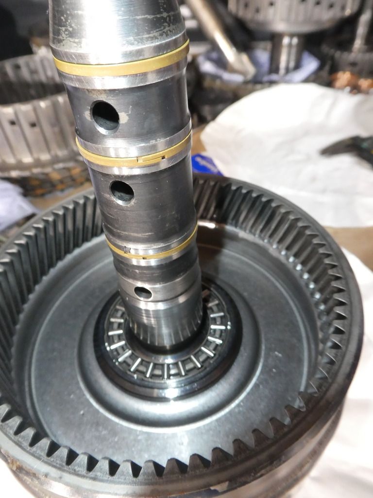
And Clutch D differs slightly in that the Ex measurement has to be taken inside the gearbox body where its held, but the principle is the same. Note though if you use the internal ledge of the gearbox as your datum face doing this one you will need a 300mm depth gauge vernier