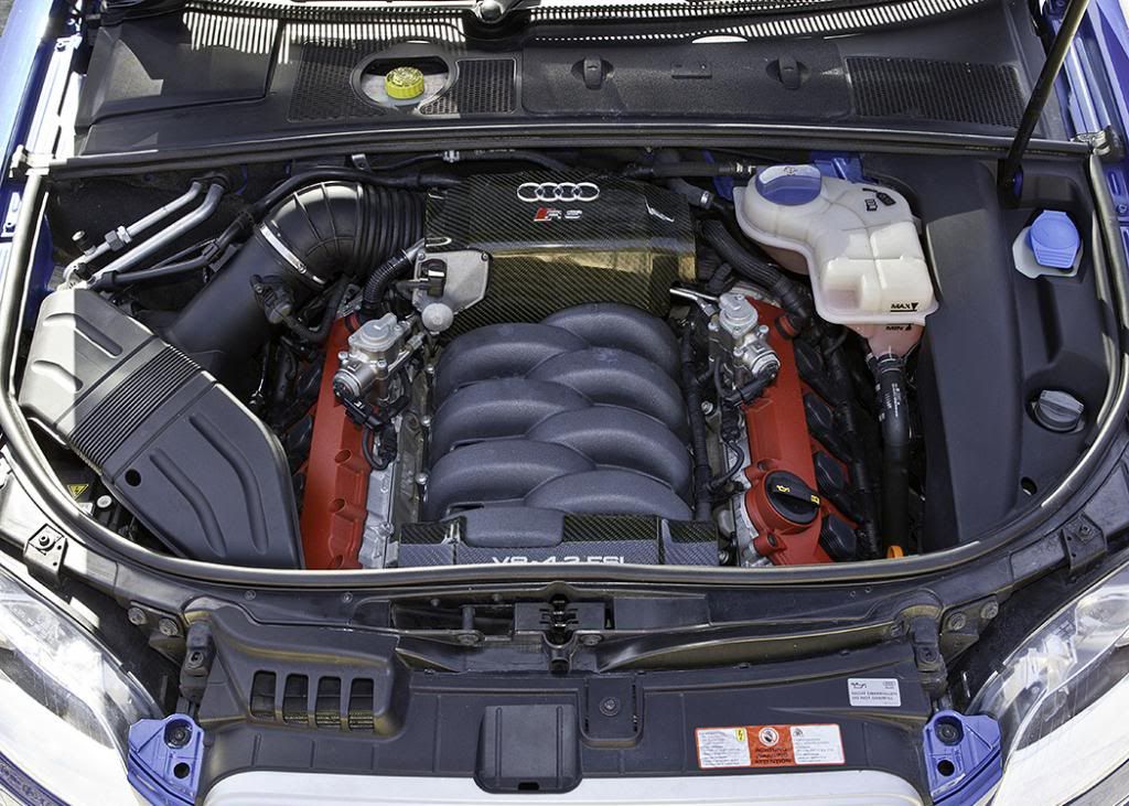
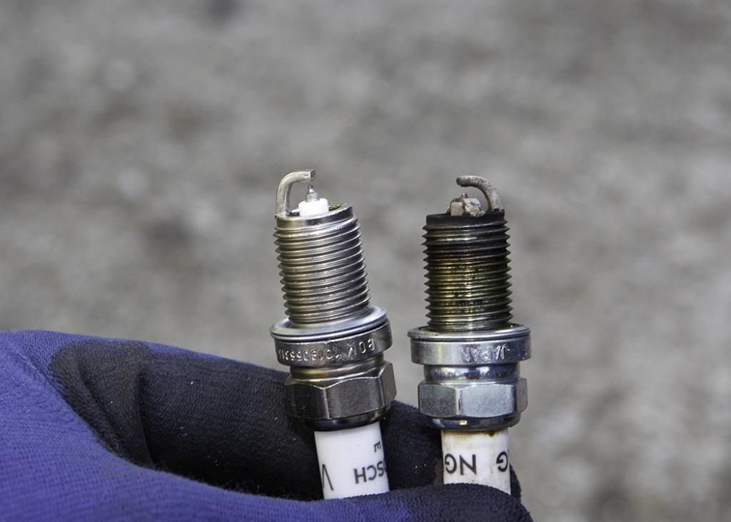
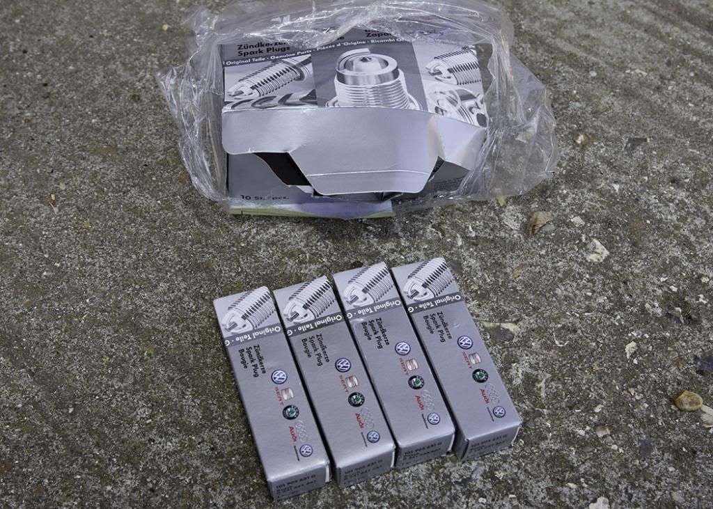
Right I did a Plug Change on my car the other day and thought I’d document the process to help anyone who was thinking of doing this job themselves. Audi recommend that the plugs are replaced every 6 years/60,000 miles - mine were approaching 6 years old and had covered 42k miles, so I felt they needed doing and I wasn't wrong:
The tools I used for this job were:
Phillips screwdriver
T30 – Torx bit
T20 – Torx bit
A driver/ratchet for the Torx bits
7mm socket (for jubilee clip, so flat blade screwdriver could be used)
¼” drive ratchet and extension bar
Spark Plug socket
½” drive ratchet and two extension bars
Torque Wrench
Ok first up, I accept no responsibility for anyone who may follow this and damage any parts/engine or indeed themselves. Overall it’s not a hard job to do, but there are points where it can be a little fiddly. If you’re really not sure about carrying this procedure out, then pay a professional to do the work for you.
However, there may be a few spanner twirlers around whom hopefully find this to be helpful.
Step 1
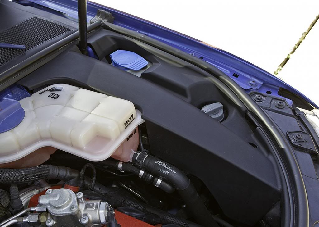
Removal of the plastic cover on the right hand side of the engine bay, this covers the PAS reservoir and the washer fluid reservoir.
Take the T30 torx bit and remove the screw located at the front, this winds into a clip located within the front slam panel. Once the screw is removed you can lift up the front part of the plastic cover and it will pull off a rubber locator next to the coolant reservoir.
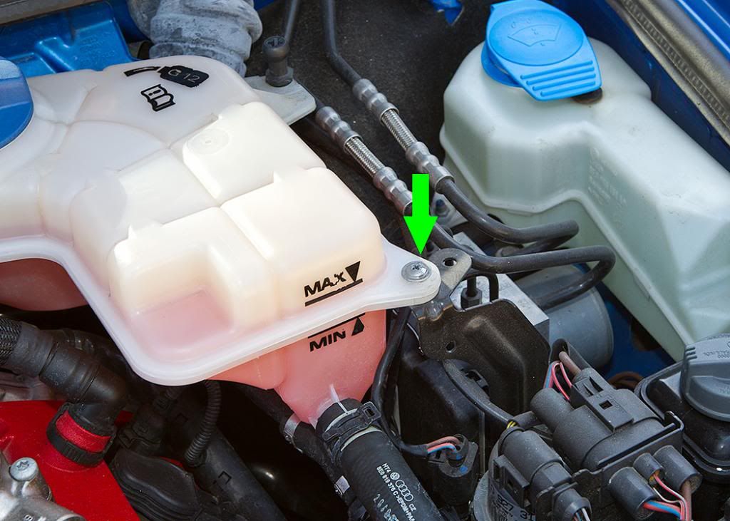
Step 2
Take Phillips screwdriver and remove the screw located on front right hand side of coolant reservoir. The official Audi documentation will then have you clamping both coolant hoses and draining the tank down. However, with a little patience further on, it isn’t necessary to do that; there’s enough slack and movement in the system, to wiggle/manoeuvre stuff around it. So I elected to just remove the screw; the choice is yours.
Step 3
Remove the Oil Dip Stick as it will be in the way. Once removed, I like to put a piece of coloured tape over the top to ensure that no foreign body drops down the tube and into the sump.
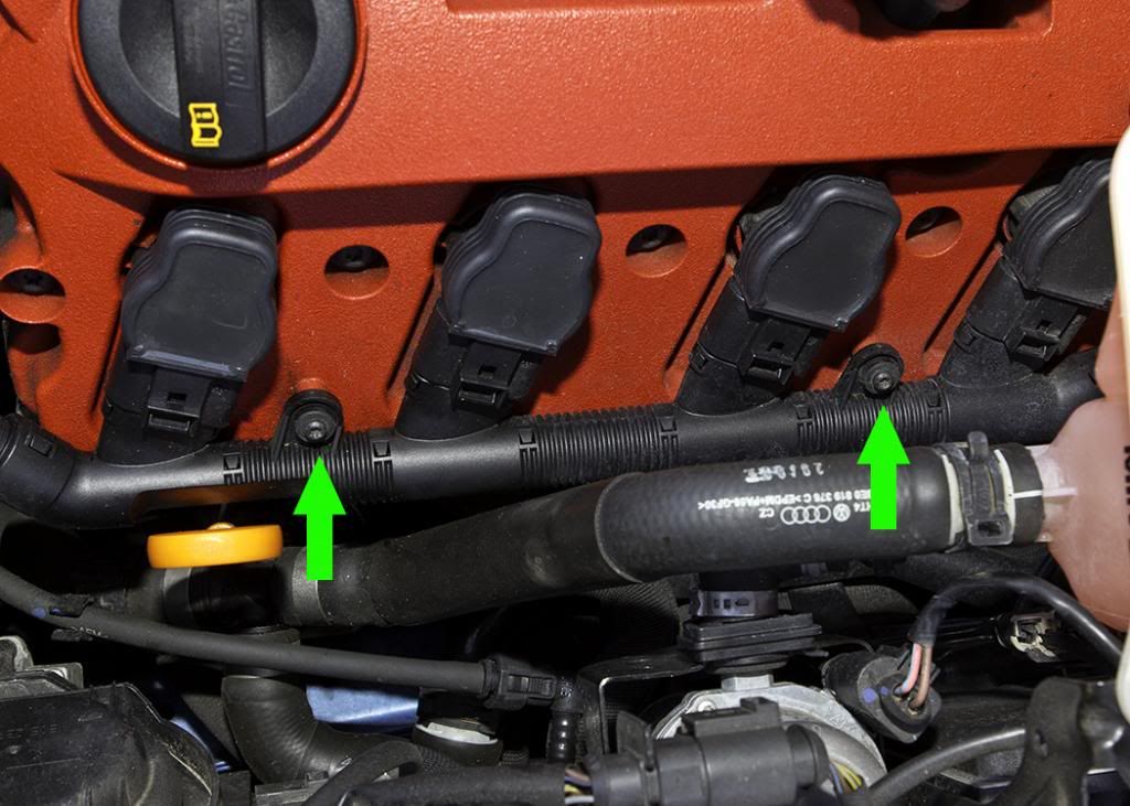
Step 4
Take the T20 torx bit and remove both screws that hold the coil pack wiring loom onto the red valve cover.
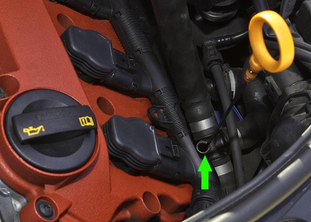
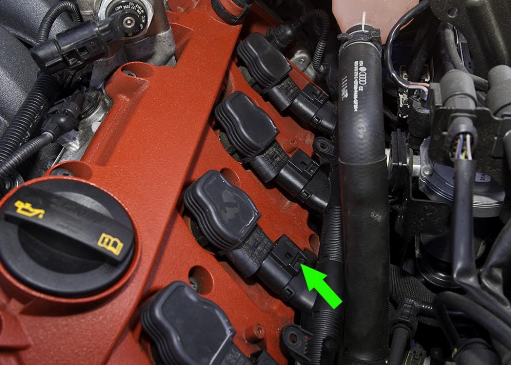
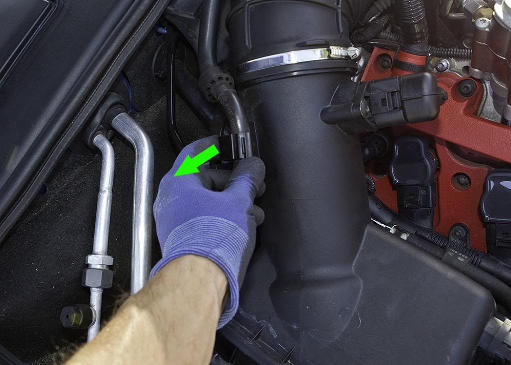
Step 5
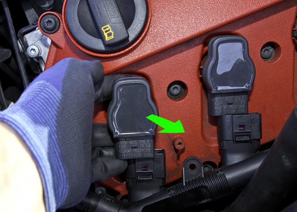
Now for the first fiddly bit – Unclipping the coil pack connectors. There is a couple of movements required together in order to undo these.
1) Press the plastic bit I have arrowed downwards firmly
2) Whilst doing the above, push the clip into coil further until you hear a feint but audible click.
3) Once you hear the click, you can then wiggle the connector off from the coil.
4) Start on the one nearest the oil filler cap first to practise as the rearmost one is harder to get onto.
5) If you are struggling with this step then walk away and get yourself a drink, come back to it 5 minutes later - a screw driver does not help here and will only serve in breaking the plastic clip.
Step 6
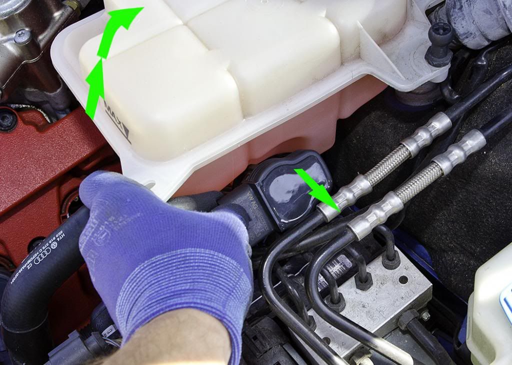
Removing the coil packs. Audi have a special tool for doing this but it can be done by hand. I squeezed my fingers under the coil pack edge as detailed in the picture (use both hands though) and then wiggle and pull up at the same time. Do this for all four coil packs with the last on being rotated 90 degrees whilst lifting the coolant reservoir as indicated in the second picture. On the underside of the coolant reservoir is a sensor; it didn’t get in my way, but for those with big hands just be mindful of its position.
Step 7
At this point with the spark plugs still fitted I chose to clean the valve cover as the coil packs can hide dirt. The step is certainly not necessary but I like my engine to look clean. The product I use is Bilt Hambers Surfex HD diluted with distilled water at a ratio of 1:5; this I spritz on, agitate with a soft bristled detailing brush and wipe off with a microfiber cloth.
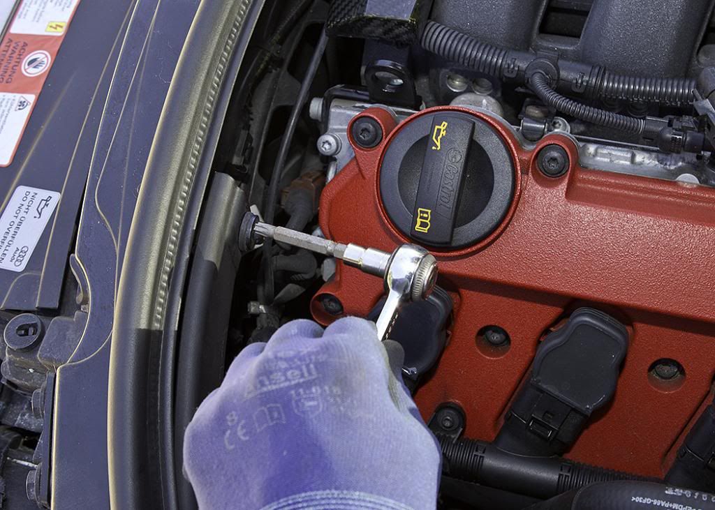
Step 8
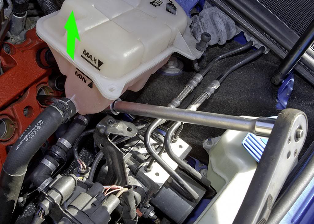
Spark Plug Removal. Take the ½” drive ratchet, spark plug socket and the extension bar, undo the plugs in an anti-clockwise direction and lift out. The rear ones were removed in much the same way as the coil packs, by lifting the coolant reservoir and adding a second extension bar as shown in the picture.
Step 9
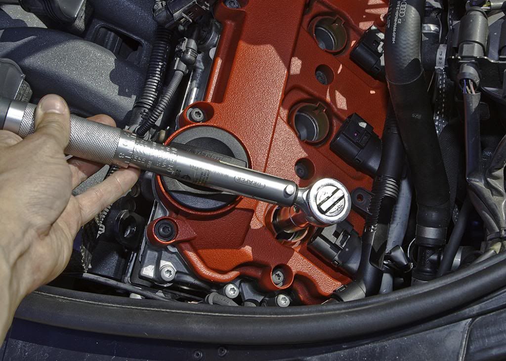
Take the new plugs and screw them back in clockwise, I like to do this by hand without the ratchet until I can no longer turn them. Set the torque wrench to 25nm and tighten them all up, then adjust the torque wrench to the final recommended setting of 30nm and tighten all four again.
Step 10
Refit everything you have just removed in steps 1-6 and have a half time break. In my case, cup of Coffee and a slice of homemade Coffee cake. Yum.

Step 11
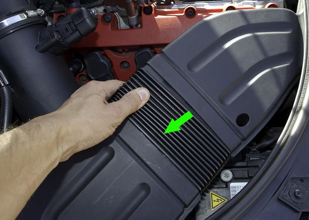
Split the air inlet feed. Use both hands and just pull back the corrugated section; it should separate from the front part fairly easily. When it comes to refitting this part later on, pay particular attention to getting all the clips both top and bottom locking in right, before pushing it back together.
Step 12
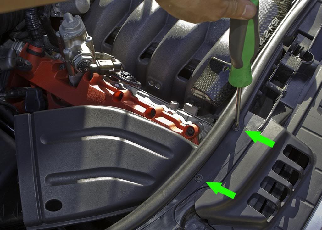
Using the Phillips screwdriver, unscrew the two screws on the front section of the air inlet feed, these are indicated in the picture. The plastic component is then free to withdraw from the slam panel housing.
Step 13
There is a hose which is clipped to the top of the airbox, opposite the MAF sensor; this can be pulled off with relative ease leaving the clip still secured to the hose.
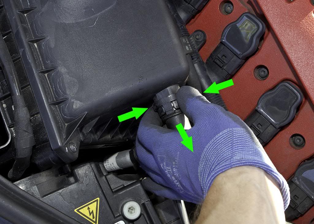
Step 14
Secondary Air Pump inlet hose. This has two clips which you press in together which release the hose to be pulled from the airbox assembly.
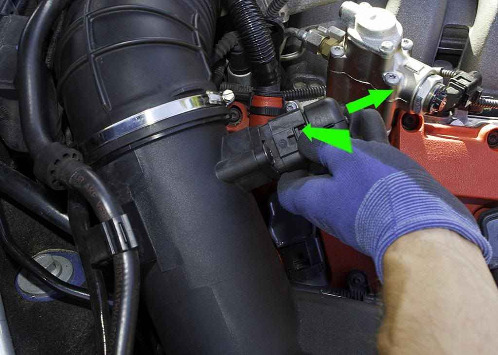
Step 15
Unplug Mass Air Flow connector. This connector works exactly the same way as the ones that plug into the coil packs. Refer back to step 5 to re-familiarise yourself if not sure.
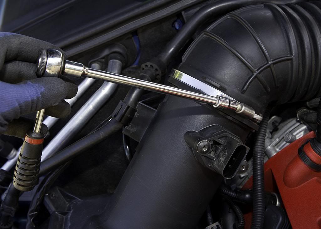
Step 16
90mm flexible air inlet hose. Take the 7mm socket and loosen the jubilee clip, this will enable you to slide the hose from the Airbox lid/MAF housing.
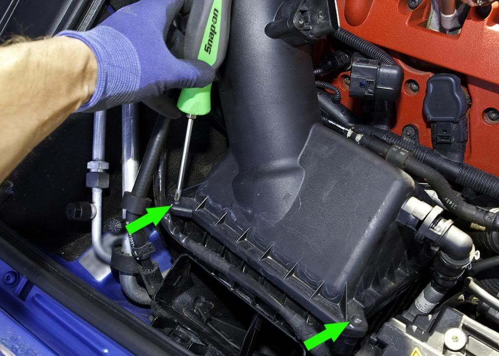
Step 17
Airbox lid. There are finally two Phillips screws that need to be removed as arrowed in the picture. Once done the housing lid will lift off and out, leaving you sufficient access space to carry out the rest of the work.
Step 18
With everything needing removal completed, you can carry out steps 4-9 as per the previous cylinder block completed earlier.
Step 19.
Once all the new plugs have been fitted and torqued correctly, you can re-install the previous parts that were removed in Steps 11-17.
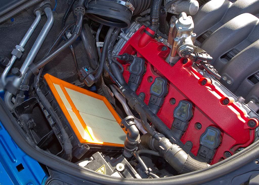
When finished, the engine bay should look like this. Job done.